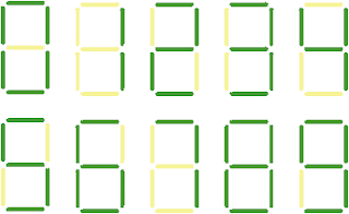
In order to display numbers, byte representing number must be sent to the PORTB and transistors must be activated by enabling corresponding PORTC pin by applying low level at the base of transistor. At any particular time, only one of the LED segments is turned on. Immediately after the segment is lit, the segment is turned off and the next segment in the implementation is turned on. Thus each digit is On-Off by controlling the anode for that display. If we do each one fast enough, we will see the entire display flicker free.


Drive a 7-Segment Display With Your FPGA Convert from Binary in VHDL and VerilogA Seven-Segment Display is an indicator commonly used by FPGA designers to show information to the user. Code to convert from binary to seven-segment display compatible can be done easily in VHDL and Verilog. There are many applications that can require the use of one or more seven-segment displays such as:.
Fallout 4 mods pc. Alarm Clock. Stop Watch. Button Count Indicator. Voltage Measurements (from Analog to Digital Converter). Many more!The GIF on the right is taken from the article about 7-segment displays. It shows what the code below will display to the user. The code takes in a 4-bit binary input.
7 Segment Display Using Common Anode Verilog 4
This allows for the decimal numbers 0-9 and the Hex Characters A-F to be displayed to the user.Both the VHDL and Verilog code work the same way. They simply use a Look-Up Table to do the decoding from the hexadecimal input to the 7-segment output. The individual segments are listed in the table below. VHDL Implementation:- File downloaded from This file converts an input binary number into an output which can get sent- to a 7-Segment LED. 7-Segment LEDs have the ability to display all decimal- numbers 0-9 as well as hex digits A, B, C, D, E and F. The input to this- module is a 4-bit binary number.